The
laboratory experiment "Three-Tank-System DTS200"
includes the technical realization of a nonlinear multi
input-multi output system (two inputs, two outputs) with two
actuators and a digital controller (nonlinear control and
decoupling).
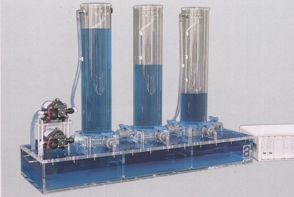
The nonlinear controlled system consists of three plexiglass
cylinders T1, T2 and T3 with the cross-sectional area A
which are interconnected in series by two connecting pipes.
The liquid (distilled water) leaving T2 is collected in a
reservoir from which pumps 1 and 2 supply the tanks T1 and
T2. All three tanks are equipped with piezo-resistive
pressure transducer for measuring the level of the liquid. A
digital controller controls the flow rate Q1 and Q2 such
that the levels in the tanks T1 and T2 can be preassigned
independently. The level in tank T3 is always a response
which is uncontrollable. The connecting pipes and the tanks
are additionally equipped with manually adjustable valves
and outlets for the purpose of simulating clogs as well as
leaks.
The documentation of the base model DTS200 includes
sections for assembly and start-up and the technical data.
The Three-Tank-System DTS200 qualifies for use in research
projects in nonlinear control and fault diagnosis. Using a
prototype of the DTS200, researchers in the department of
measurement and control at the University of Duisburg have
successfully tested methods of nonlinear decoupling and
model based fault diagnosis.
For such advanced research projects the following options
are available:
The Option 200-02 extends the basic
version of the DTS200 by a plug-in card for a PC with ISA
slot. The associated practical course program running under WINDOWS (Win 3.1/Win 95) is designed for engineering student
laboratories or demonstrations.
(Win 3.1/Win 95) is designed for engineering student
laboratories or demonstrations.
|
The adjustment of controller
parameters, the determination of characteristics or the
recording of step responses with respect to set-point
changes or disturbances can be selected by means of a menu.
The graphic ouput of recorded data may be sent to a window.
Its content may be printed, saved as a WMF file or copied
into the clipboard.
The documentation is extended by sections for the
theoretical background and the mathematical model of the
plant as well as guidelines for the practical course with
solutions. The described laboratory experiment is suitable
for students at all levels of process control engineering.
With the option 200-03 a standard
controller program in C++/Pascal-Source in combination with
a library of PC Input/Output routines is available. The
controller program can be modified by the user for research
purposes. The Input/Output routines contain among other
things the driver for the A/D-D/A converter card which come
with option 200-02. The range of functions and operating
possibilities of the standard controller program is
equivalent to the above mentioned practical course program.
The Borland C++ compiler V4.52 as well as Delphi V1.0 are
required.
An electrical disturbance-module (option 200-05)
allows the simulation of eight different faults affecting
the sensors, the plant and the actuator. For the three
sensors total failures can be simulated by switches while
scaling errors can be adjusted by potentiometers. A
variation of the actuator amplification can be achieved by
attenuating the control signals for the two pumps. The
attenuation can be adjusted using potentiometers. The last
manipulations simulate two further component failures
besides the mentioned clogs and leaks.
For own developments with the laboratory experiment
"Three-Tank-System DTS200" the following extension
kits are available:
- Option 200-06a Electrical
control valve as coupling valve between the tanks.
- Option 200-06b Electrical control valve as drain
valve.
- Option 200-07a Like Option 200-06a but with
potentiometer output.
- Option 200-07b Like Option 200-06b but with
potentiometer output..
- Option 200-08 Venturi
meter for flow measurements.
- Option 200-09 Adapter
Box for control valves contains free slots for max.
6 Converter Modules from Opt. 200-10.
- Option 200-10 Converter Module for Adapter Box.
Technical data are subject to change (Date
03-February-1999)
|