The
laboratory experiment "TS201 Tank System" contains
the technical implementation of a nonlinear, single-variable
system (one input variable and one output variable), an
actuator for the pump and, as standard, an analog controller
(nonlinear controller).
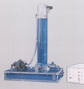
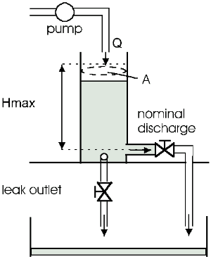
The nonlinear controlled member consists of a plexiglass
cylinder T of cross-sectional area A. The liquid (distilled
water) flowing from T is collected in a reservoir from which
the pump supplies the tank T. A piezo-resistive pressure
transducer is located on the tank to measure the height of
the liquid level. An analog controller controls the volume
flow rate Q of the pump such that the liquid level in the
tank T remains constant. In addition the tank is fitted with
a continually variable manual valve to simulate a leak.
In the standard version the laboratory experiment is
supplied with a special analog controller. The analog
controller is a microelectronic circuit integrated into a
19" housing together with the actuator. All control
parameters can be set on the front panel using
potentiometers representing the coefficients. Command and
disturbance variables are switched in using switches.
Sockets are provided for the measurement of the relevant
system variables. The associated documentation contains
appropriate instructions for the installation as well as the
technical data. This standard version is therefore suitable
as a practical experiment for students in all stages of
control engineering. |
The extended PC version consists
of an executable controller program running under WINDOWS
(Win 3.1/ Win95) in combination with an
A/D-D/A-converter-card for a PC. The program (option
201-01) provides plant identification, free adjustment
of controller parameters and setpoint as well as acquisition
and graphic output of the control signal and the measured
liquid level. The graphic output of recorded data may be
sent to a window. Its content may be printed, saved as a WMF
file or copied into the clipboard. The executable program
requires an IBM-AT-compatible PC with ISA slot and the
operating system MS- Windows. The documentation is expanded
by the sections guidelines for a practical course and
solutions as well as operating instructions for the
controller program at hand.
The option 201-02 consists of the C++/Pascal source
code of the PC controller program with library functions for
PC input/output. The input/output routines contain among
other things the driver for the A/D-D/A converter card which
comes with option 201-01. With this extra software for
special control algorithms, supervision and fault detection
can be developed by the user. The Borland C++ compiler V4.52
as well as Delphi V1.0 are required.
For own developments with the laboratory experiment
"Tank-System TS201" the following extension kits
are available:
- Option 201-03 Electrical
control valve .
- Option 201-04 Like Option 201-03 but with
potentiometer output.
- Option 201-05 Venturi
meter for flow measurements.
- Option 201-06 Adapter
Box for control valves contains free slots for max.
6 Converter Modules from Opt. 201-07.
- Option 201-07 Converter Module for Adapter Box.
Technical data are subject to change (Date
13-April-1999)
|