The laboratory
experimental setup "Speed Control with Variable
Load" contains the technical realization of a nonlinear
single-input/single-output system with appropriate actuator,
sensors, measurement outputs and the possibility to connect
different controllers.
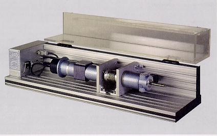
The plant is represented by a permanently exited DC-motor
(M1) of which the input signal (armature current) is
provided by a current control loop. Its servo amplifier
allows the 4 quadrant mode. The sensors for the output
signal (speed) are a tacho generator (T) and an incremental
encoder (I). The free end oft the motor shaft is fixedly
coupled (K) to the shaft of a second, identical motor (M2).
This motor is used as a generator. Its output current is
freely adjustable. The second end of the generator shaft
provides the possibility to mount an additional mass.
The motors are mounted on top of aluminium profiles. The
system is ready to operate and is plugged to the appropriate
electronics using only one connector. The motors and all of
the rotating parts are protected by a transparent plexiglass
cover which lets down.
In the standard version the system DR300 consists of the
mechanical setup and a 19" case. It contains the servo
amplifiers, built by current controllers, for the motor and
the generator, the signal adaption unit, power supplies and
a module with measurement outputs. A detailed documentation
is included.
The option 300-01 extends the system by an
analog PI-controller which is integrated in the case. The
speed setpoint of the motor and the load current of the
generator are adjustable by providing DC voltage in the
range +/-10 Volt to BNC jackets. The measurement signal for
the controller is provided by the tacho generator. The
proportional and integral portion of the controller can be
adjusted by coefficient potentiometers.
|
The option 300-02 extends the
standard version of the DR300 by an additional card for an
IBM-AT compatible PC. It contains A/D-D/A converters,
digital input/output channels and an incremental encoder
input channel. The included practical experiment "PI
Speed Control" deals with parameter settings for
PI-controllers using Bode diagrams and optimal compensation
methods with respect to the plant parameters which are
determined during the experiment. The PC program is
controlled by pull down menus which are activated by a mouse
and/or by keyboard (Turbo-Vision desktop of Borland). It
allows a comfortable identification of the plant parameters
using the recorded step responses of the open control loop.
A PI-controller is implemented to control the system. Its
parameters can be changed online. The control performance
with respect to reference and disturbance behaviour can be
examined by recording the system response after variations
in the reference and the disturbance signals. The input
signals are adjustable with periodical behaviour. Graphic
output of the recorded signals to the monitor of the PC, to
an HP-compatible plotter or an Epson-compatible printer
provides the evaluation of the results. The program allows
to store the adjusted or measured plant and controller
parameters to an ASCII file. Those data can be load later
on.
The option 300-03 extends the program
described under option 300-02 by a Fuzzy-controller. The
practical experiment "Fuzzy Speed Control"
explains the concept of a Fuzzy-control. It can be used as
an extension to the practical experiment "PI Speed
Control". An ASCII file is used to define any fuzzy set
and rule. A second, virtual input signal, the angular
acceleration, is computed from the angular velocity of the
motor. The comparison of Fuzzy-control and PI-control can be
easily performed by switching the controller mode.
The option 300-04 extends the system by an
electrical disturbance module which is mounted in the
19"-case. Its front panel contains switches and
potentiometers to simulate failures. The manipulated signals
are the tacho generator signal and the control signal for
the servo amplifier of the motor. Both signals can be scaled
or switched off.
The option 300-05 consists of the C++-
source code with documentation of the program mentioned
under opt. 300-03 including libraries for the graphic output
and the fuzzy operations . It is useful for software
extensions to study for instance position control, model
based failure detection, comparison of tacho generators
versus incremental encoders etc. The Borland C++ compiler
with the Turbo-Vision library is required to generate an
executable program.
Technical data are subject to change (Date
22-February-1996) |