The laboratory
experimental setup "Ball and Beam" contains the
technical realization of a nonlinear plant together with an
actuator and a digital controller using observer based state
feedback.
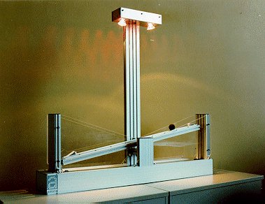
The nonlinear plant is represented by a ball laying on a
beam with an adjustable angle. The ball can roll upon the
beam within a distance of 1m. By a toothbelt, a toothwheel
and a clutch mounted on the shaft of a DC-motor the beam can
be driven such that the ball is stabilized at a preassigned
position. The stabilization of the ball is accomplished by a
digital controller. Based on measurements, the controller
generates a suitable signal which controls the DC-motor by
an electronic servo amplifier. The measurements are the
angle of the beam obtained by an incremental encoder and the
ball position obtained by a CCD-camera. The system is ready
to operate after connecting to the electronic actuator. All
the moving parts are covered by transparent plexiglass.
In a standard version the experimental setup BW500 includes
the mechanical setup as well as a 19" casing which
contains the servo amplifier for the DC-motor, the signal
adaption unit as well as power supplies. A detailed
documentation of the system is included in the shipment.
The Option 500-02 extends the standard
version of the BW500 by an adapter card ready to plug in an
IBM-AT-compatible PC with ISA slot and a controller program (MS-WINDOWS).
The card provides digital input/output channels, D/A
converters output channels as well as input channels for
incremental encoder signals. The controller program (Win 3.1
/ Win95) allows for a menu-driven operation of the
laboratory experiment.
The control algorithm of the "Practical
Program" consists of state feedback with estimation of
the beam angular acceleration, estimation of the ball speed
and a disturbance observer to suppress the effects of the
friction. The parameters of the controller and of the
observers are comfortable adjustable. The controller
performance is examined by recording the systems response to
to changes of the reference and disturbance signals. The
signal shapes of the input signals are adjustable as
periodic time functions. Measurements of the input and
output signals can be represented in a graphic on the PC
screen. The graphic ouput of recorded data may be sent to a
window. Its content may be printed, saved as a WMF file or
copied into the clipboard. The program allows for storing
the adjusted or determined parameters of the plant and of
the controller in an ASCII file. Those data may be loaded
again later on.
The Option 500-03 extends the program
described with Option 500-02 by a fuzzy controller. This
program is useful for learning the concept of a fuzzy
control. The comparison of the fuzzy controller with the
state feedback controller is easily obtainable by switching
the controller mode.
The Option 500-05 consists of the
C++/Pascal source files with documentation of the PC
controller program described with Option 500-02 including
library functions for fuzzy operations (ref. Option 500-03)
and graphic output. With this option the software may be
extended for further studies on i.e. model based fault
detection, different observer concepts etc. The Borland C++
compiler version 4.52 as well as Delphi V1.0 are required to
generate an executable program.
Option 500-06 contains a 13 cm monochome
monitor suitable for display of the camera image und for
service. The monitor will be delivered with a power supply
and a connection cable to the actuator.
Technical Data: Dimensions: Length 1160mm, Width 210mm,
Height 1025mm Motor data: 24V, 2A, 30W, 9,6Ncm (3000 Rpm)
Technical data are subject to change (Date
15-April-1999)
|